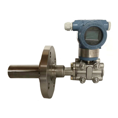
Liquid level pressure transmitter
- Tel:0550-7989666、0550-7989999
- Fax:0550-7989666
- Mail:tkjd@tiankang.com
Description
I. Introduction
Capacitive differential pressure transmitter and long distance differential pressure transmitter are new products in differential pressure transmitter. It is widely used in petroleum, chemical, metallurgy, electric power, light industry, building materials, scientific research and other enterprises and institutions to achieve various kinds of fluid pressure measurement. Throttling devices are used to detect liquid, steam and steam, as well as the flow of viscous, precipitated or easily crystallized particles. It can also detect differential pressure, gauge pressure and interface, and also detect the liquid in open container or pressurized container. Body level.
Two, characteristics
1. Small size and light weight. Because its components are few and its structure is simple, and the transformation of differential pressure, displacement and capacitance signal is linked together, the volume is greatly reduced and the weight is reduced.
2, high accuracy. Because there is no mechanical transmission and friction, and the relative value of capacitance value is relatively large, the accuracy is easy to do.
3. Good reliability. Due to the small number of movable parts, the measuring unit is a fully enclosed solid structure, the electronic components are screened through strict aging, and the special bead connector is adopted, thus greatly improving the reliability of the transmitter.
3, the range can be adjusted with a large and positive and negative transfer structure. Range adjustable range is greater than 6:1, zero range external connection can be adjusted.
4, overload performance is good. Inside the sensor, a concave arc surface overload protection structure with simple structure and reliable performance is adopted.
5, with adjustable damping device, it can be used for pulsating fluid measurement.
6, transmitter for flameproof and intrinsically safe type used in dedicated circuit, the output of the circuit is less than 30mA.
7, transmitter can be attached to 100% pointer, LCD LCD, LED digital tube display, on-site reading is very convenient.
8, transmitter uses 4~40mA DC standard current signal output, two-wire system, with load, anti-interference ability.
Three, technical parameters
medium | Liquid, gas and steam |
measuring range | 0~0.1KPa to 0~40Mpa |
Accuracy grade | 0.2, 0.1, 0.075 |
output signal | 4~20mA |
Power supply | DC24V |
Service temperature | -20~80 C |
Storage temperature | -20~80 C |
relative humidity | 0~90% |
Protection level | IP65 |
explosion-proof | DIIBT4, iaIICT6 |
Four, selection table
EBY3051 | Capacitive pressure transmitter | |||||
KO | Ordinary type | |||||
KB | Explosion proof type | |||||
Zero | negative pressure | |||||
One | Gauge pressure GP | |||||
Two | Differential pressure DP | |||||
Three | Absolute pressure AP | |||||
Four | Gao Jing differential pressure HP | |||||
Five | Micro differential pressure DR | |||||
Six | Differential pressure QP | |||||
Seven | Liquid level transmitter LT | |||||
One | 0-0.06~0.3KPa | |||||
Two | 0-0.25~1.5KPa | |||||
Three | 0-1.2~10KPa | |||||
Four | 0-6.0~40.0KPa | |||||
Five | 0-30.0~180.0KPa | |||||
Six | 0-160~1000.0KPa | |||||
Seven | 0-0.4~2.5MPa | |||||
Eight | 0-1.6~10.0MPa | |||||
Nine | 0-4.0~25.0MPa | |||||
Zero | 0-7.0~40.0MPa | |||||
Zero | Standard form | |||||
One | Single flanges | |||||
Two | Flanged flanges (range greater than 6KPa) | |||||
Three | Single insert flange type | |||||
Four | Double insert flange type (range greater than 6KPa) | |||||
Five | One flattened and one inserted flange type (with a range of more than 6KPa). | |||||
One | 4-20mA output signal | |||||
Two | 4-20mA output signal +HART protocol | |||||
Accessories and material code
Code name | Meaning | ||
M3 | Digital LCD display head | ||
E1 | Common cable connector | ||
E2 | Explosion proof cable connector | ||
B1 | Pipe bent bracket | ||
B2 | Disk mounted bent bracket | ||
B3 | Pipe mounting bracket | ||
D1 | The flange side exhaust / drain valve is on the upper side. | ||
D2 | Flange side exhaust / drain valve at lower part. | ||
G1 | Waist flange | ||
G2 | Welded pipe Street | ||
G3 | Integrated three valve group | ||
G | Less than 200 degrees centigrade (high temperature silicone oil) | ||
Anticorrosive material | Structural materials | ||
Flange joint | Exhaust / drain valve | Isolation diaphragm | |
F12 | carbon steel | 316L | 316L |
F13 | carbon steel | Haste C | Haste C-276 |
F14 | carbon steel | Monel | Monel K-500 |
F15 | carbon steel | 316L | tantalum |
F22 | 316L | 316L | 316L |
F23 | 316L | 316L | Haste C-276 |
F24 | 316L | 316L | Monel K-500 |
F25 | 316L | 316L | tantalum |
F26 | 316L | 316L | Haste B-2 |
F33 | Haste C | Haste C | Haste C-276 |
F35 | Haste C | Haste C | tantalum |
F44 | Monel | Monel | Monel K-500 |
F47 | Monel | Monel | 3YC25 |
Note: M3 and F22 are standard configurations.


