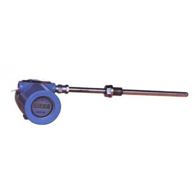
Integrated explosion-proof thermal resistance
Description
I. product introduction
The integrated explosion-proof thermal resistance is usually used in conjunction with display instruments, recording instruments, electronic computers and so on. The output is 4 ~ 20mA. Direct measurement of liquid, steam and gas medium and solid surface temperature in 0~1800 degree range of production processes.
Two. Main features of products
The second line output is 4 ~ 20mA, and the anti-interference ability is strong.
Save the cost of compensation conductor and installation temperature transmitter.
The measuring range is large.
Automatic compensation of cold end temperature and nonlinear correction circuit.
Three. Working principle
Integrated explosion-proof thermal resistance using gap flameproof principle, when the cavity exploded, it can extinguish and cool the flame through the joint gap, so that the temperature of the flame after the explosion can not reach the outside of the cavity, so that the temperature can be measured. The thermoelectric potential (resistance) produced by the thermocouple (resistance) produces an unbalanced signal through the bridge of the temperature transmitter. After amplification, it is converted to a 4 to 20mA DC electrical signal to the working instrument, and the working instrument displays the corresponding temperature value.
Four. Technical parameters
Executive standard
IEC584 IEC1515 IEC751 JB/T5518-91 JB/T7391-94
Five. Temperature range and tolerance (thermocouple)
Model | Graduation | Allowable error and mate grade | |||
Level I | Level II | ||||
Allowable difference | Temperature range C | Allowable difference | Temperature range C | ||
WRNB | K | + 1.5 C | -40 ~ +375 | + 2.5 C | -40 ~ +333 |
0.004 t | 375~1000 | 0.0075 t | 333~1200 | ||
WRMB | N | + 1.5 C | -40 ~ +375 | + 2.5 C | -40 ~ +333 |
0.004 t | 375~1000 | 0.0075 t | 333~1200 | ||
WREB | E | + 1.5 C | -40 ~ +375 | + 1.5 C | -40 ~ +333 |
0.004 t | 375~800 | 0.004 t | 333~900 | ||
WRFB | J | + 1.5 C | -40 ~ +375 | + 1.5 C | -40 ~ +333 |
0.004 t | 375~750 | 0.004 t | 333~750 | ||
WRCB | T | + 1.5 C | -40- ~ +125 | + 1 c | -40 ~ +333 |
0.004 t | 125~350 | 0.0075 t | 133~350 | ||
WRPB | S | + 1 c | 0 ~ +1100 | + 2.5 C | 0~600 |
+ [1+0.003 (t-1100)] | 1100~1600 | 0.0025 t | 600~1600 | ||
Note: t is the measured temperature value of the sensing element.
Temperature range and tolerance (thermal resistance)
Model | Graduation | Temperature range C | Accuracy grade | Allowable deviation |
WZPB | Pt100 | -200 ~ +500 | Class A | (0.15+0.002|t|) |
Level B | (0.30+0.005|t|) | |||
WZCB | Cu50 | -50 ~ +100 | - | (0.30+0.006|t|) |
Cu100 |
Note: t is the measured temperature value of the sensing element.
Explosion proof grade:
Flameproof: dIIBT4, dIICT5, dIICT6
Intrinsically safe form: iaIICT6
Six. Other parameters
Output signal: 4 ~ 20mA, load resistance 250 ohm, transmission wire resistance 100 ohm.
Output method: two-wire system
Tolerance level: 0.1; 0.2; 0.5
Power supply: 24V.DC + 10%
Protection level: IP65
Thermal response time
When the temperature changes step by step, the current output signal of the instrument changes to 50% of the time required to achieve the step change. Usually, tau 0.5 indicates that when the step response time of the temperature transmitter is less than 1/5 of the thermal response stability time of the thermocouple (resistance), the thermal response time of the thermocouple (resistance) is used as the thermal response time of the instrument; and when the temperature is changed step by step, the time of the step response of the temperature transmitter is less than 1/5 of that of the thermocouple.
When the step response time of the temperature transmitter is not more than 1/2 of the thermal response stability time of thermocouple (resistance), the thermal response time of the temperature transmitter is used as the thermal response time of the instrument. 0.5.


